Presentation on our journey
Circuit Design
A circuit has a few important and basic components . There is the power source , the wires , resistors and the output source ( eg . A light bulb ) . In circuit design , we have to try to rearrange all these components so that the circuit draws the least energy .
Terminologies
Terms | Description | Unit of measurement |
Charge | A quantity | Coulomb (Q) |
Current | Rate of flow of electric charge . If charge particles were to move from point A to B , current would be the number of particles passing through point B per second . | Amperes (A) OR Coulomb/sec |
Voltage | The energy causing the current / the electric particles to move | Volts (V) |
Resistance | Restricts how much current flows through | Ohms (Ω) |
***Important to note :
The Ohms law is the basic law that governs the whole world of electronics . It describes the relationship between Current , Voltage and Resistance .
Ohms law :
V = I x R
In which , V = Voltage , I = Current and R = resistance .
Equipments and Components
 |
| A Voltage source with its different parts |
This basically converts the AC from the power sockets into DC as the circuit that we are going to build can only work on DC . There are various knobs for us to adjust the voltage , either in big or small intervals . There are also other knobs and buttons , as seen in the picture on the right .
2. Multimeter
 |
| A multimeter with its different parts |
This instrument is used to measure Voltage , Current and Resistance .
It is purely for measurement so it does do affect the circuit in any way .
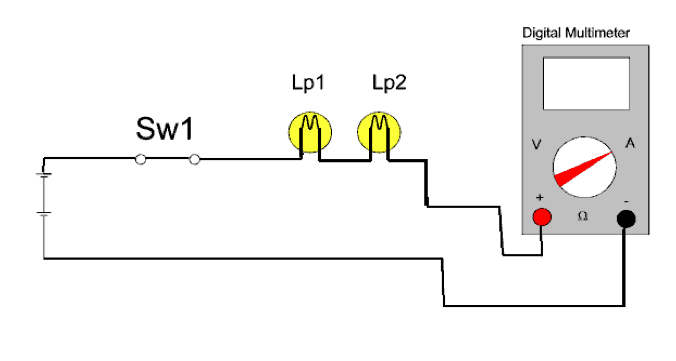
2.1 Measuring Voltage with a Multimeter
 |
| Measuring voltage |
2.2 Measuring Current with a Multimeter
 |
| Measuring Current |
Before anything , check and make sure that the Multimeter is set to the current/resistance measurement . When measuring current , everything must be arranged in a SERIES arrangement . When the Multimeter is used as an ammeter , it has a very small impedance ( resistance ) and will result in a small voltage drop across the multimeter’s leads.
 |
| Measuring Resistance |
Before anything , check and make sure that the Multimeter is set to the current/resistance measurement . When measuring resistance , everything must be arranged in a PARALLEL arrangement . To measure resistance across a resistor , connect the positive terminal on either one end of the lead and the negative terminal on the other end lead .
 |
| Standard EIA Color Code Table |
 |
| A resistor , as compared to a handphone |
3. Resistors
This component resists the flow of electrical current . The voltage of the current is dropped as it flows through one terminal to the next terminal of the resistor . Resistors add the safety element to the circuit as it maintains a known safe current for the circuit . Resistance is measured in ohms . A high ohm rating means a high resistance to current . Because resistors are so small , colour bands are imprinted on the resistors itself which allows us to tell the ohm rating of that resistor . The bands are de-coded using the ‘ Standard EIA Color Code Table ‘ .
4. Transistor
It is basically a switch that is activated on the voltage/current it receives . The transistor connects circuits from its “c” terminal to the circuits attached to its “E” terminal depending on the voltage/current applied to its “B” terminal . If the voltage/current is high , the switch is turned ON . Otherwise , it is OFF .
5. Light Dependent Resistor (LDR)
LDR or photoconductor is a resistor with varying resistance according to light intensity . For this particular LDR , resistance decreases when light intensity increase .
6. Force Sensitive resistor (FSRs)
FSRs are resistors with varying resistance according to force applied . The resistance of the FSR decreases when the the force increases .
7. Potentiometer / Rheostat
It is a three-terminal resistor . The dial on the Potentiometer is mechanically rotated to determine the resistance . Rheostat is used to adjust volume while a Potentiometer is used to adjust the brightness of lamps .
8. Light Emitting Diode (LED)
LED is a special semiconductor that convert light directly from electricity . We used this in our circuits to check on whether there is current flowing through the circuit .
9. Breadboard
It is a construction base for prototypes . It is useful for experimenting as no soldering is required and is reusable . This give us room for us to make mistakes . Refer to picture on the side for the breadboard connection .
9.1 Resistors in Parallel on Breadboard
9.2 Resistors in Series
Experiments
1: Knowing the Voltage Source and multimeter
What we got out of this experiment was how to use the voltage source as well as the multimeter . We had to fine tune on the Voltage source in order to get those smaller voltages such as 1V . To measure with the multimeter we had to make sure that the arrangement was parallel .
2: Knowing the resistance - colour codes
We learnt how to read the bands on the resistor in this experiment .
The resistor that we got was one with Brown , Black , Orange and Gold bands , in respective orders .
So , referring to the table , we derived that the resistance was :
[ ( 10 x 10³ ) x ±5% ] ohms
= ( 10 000 ± 500 ) ohms
3 : Knowing the Ohm’s Law
We learnt how to manipulate the Ohm’s Law , which means shifting the values around to find what we want . In this experiment , with an un-changed resistor , the current increased as the voltage increased .
4: Knowing the Series and parallel connections of resistors
Through this experiment , we discovered how to find out the total resistance of several resistors in both parallel and series connections .
For Series connection ,
R1 + R2 = RT
For Parallel connection ,
RT = R1R2 / R1+R2
We also realised that these two equations could be derived from the Ohm’s Law.
5-8 : Connecting the LED , Transistor , FSR and LDR in circuits
For these few experiments , we learned how to successfully connect these componenets in a circuit and also learn how each component worked .